İçindekiler
Daikin air conditioner error codes, are error codes that appear on indoor and outdoor units for the service to repair your DAIKIN air conditioner.
DAIKIN air conditioners have split multi and Vrv systems and we will help you to correct these errors.
Before calling the Air Conditioner Service, make sure that you operate your air conditioner in the correct mode and temperature range and that the energy switch of your air conditioner is intact.
Error detection with DAIKIN air conditioner remote control
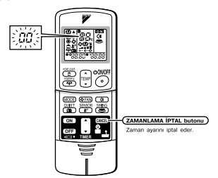
- When the TIMER CANCEL button is pressed for 5 seconds, a The “00” mark flashes.
- Press the TIMER CANCEL button repeatedly until a continuous beep is heard.
- • The code sign changes as shown below and warns with a long beep.
- A short beep followed by two consecutive beeps indicates unsuitable codes.
To cancel the code display, press and hold the TIMER CANCEL button for 5 seconds.
The code display will also be canceled if the button is not pressed for 1 minute.
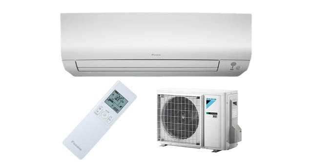
Daikin Split Air Conditioner Error Codes
| ERROR CODE | DESCRIPTION | |
| SYSTEM | U0 | LACK OF REFRIGERANT GAS |
| U2 | LOW VOLTAGE OR MAIN CIRCUIT OVERVOLTAGE | |
| U4 | COMMUNICATION FAILURE BETWEEN INDOOR AND OUTDOOR UNIT | |
| INDOOR | A1 | INDOOR UNIT PCB FAULT |
| A5 | HIGH PRESSURE CONTROL OR FROST PROTECTOR | |
| A6 | INDOOR FAN MOTOR FAULT | |
| C4 | FAULTY HEAT EXCHANGER TEMPERATURE SENSOR | |
| C9 | FAULTY INTAKE AIR TEMPERATURE SENSOR | |
| CF | HIGH PRESSURE SENSOR FAULT | |
| OUTDOOR | EA | COOL-HEAT TRANSITION ERROR |
| E5 | OL STARTED | |
| E6 | FAULTY COMPRESSOR STARTING | |
| E7 | DC FAN MOTOR FAILURE | |
| E8 | OPERATION STOPPING DUE TO OVERCURRENT INPUT DETECTED | |
| F3 | HIGH TEMPERATURE DISCHARGE PIPE CHECK | |
| H6 | STOPPING OPERATION DUE TO FAULTY POSITION DETECTION SENSOR | |
| H8 | CT ABNORMALITY | |
| H9 | FAULTY INTAKE AIR TEMPERATURE SENSOR | |
| J3 | FAULTY DISCHARGE PIPE TEMPERATURE SENSOR | |
| J6 | FAULTY HEAT EXCHANGER TEMPERATURE SENSOR | |
| L4 | HIGH TEMPERATURE IN CONVERTER CIRCUIT COOLER | |
| L5 | OUTPUT OVERCURRENT | |
| P4 | FAULTY CONVERTER CIRCUIT COOLER TEMPERATURE SENSOR |
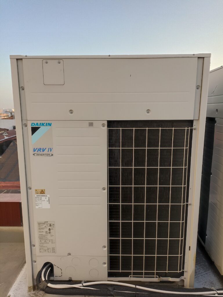
Daikin VRV System Error Codes
| ERROR CODE | DESCRIPTION |
| A0 | External protection device activated |
| A1 | EEPROM error (indoor) |
| A3 | Drainage system malfunction (outdoor) |
| A6 | Fan motor failure (indoor) |
| A7 | Engine failure of swing door (indoor) |
| A9 | Expansion valve failure (outdoor) |
| AF | Drain malfunction (indoor unit) |
| AH | Filter dust chamber malfunction (indoor) |
| AJ | Capacity setting failure (indoor) |
| C1 | Transmission failure between main PCB and sub PCB (indoor) |
| C4 | Heat exchanger thermistor failure (indoor; liquid) |
| C5 | Heat exchanger thermistor failure (indoor; gas) |
| C9 | Intake air thermistor malfunction (indoor) |
| CA | Extract air thermistor malfunction (indoor) |
| CE | Motion detector or floor temperature sensor malfunction (outdoor) |
| CJ | User interface thermistor failure (indoor) |
| E1 | PCB failure (outdoor) |
| E2 | Current leakage detector actuated (outdoor) |
| E3 | High pressure switch actuated |
| E4 | Low pressure switch actuated |
| E5 | Compressor lock detection |
| E7 | Fan motor failure (outdoor) |
| E9 | Electronic expansion valve malfunction (outdoor) |
| F3 | Discharge temperature fault (outdoor) |
| F4 | Abnormal suction temperature (outdoor) |
| F6 | Refrigerant overcharge detection |
| H3 | High pressure switch malfunction |
| H4 | Low pressure switch malfunction |
| H7 | Fan motor problem (outdoor) |
| H9 | Ambient temperature sensor malfunction (outdoor) |
| J1 | Pressure sensor malfunction |
| J2 | Current sensor malfunction |
| J3 | Discharge temperature sensor malfunction (outdoor) |
| J4 | Heat exchanger gas temperature sensor malfunction (outdoor) |
| J5 | Suction temperature sensor malfunction (outdoor) |
| J6 | Defrost temperature sensor malfunction (outdoor) |
| J7 | Liquid temperature sensor (after subcooling HE) failure (outdoor) |
| j8 | Fluid temperature sensor (coil) malfunction (outside) |
| j9 | Gas temperature sensor (after subcooling HE) failure (outdoor) |
| JA | High pressure sensor malfunction (S1NPH) |
| JC | Low pressure sensor malfunction (S1NPL) |
| L1 | INV PCB abnormal |
| L4 | Wing temperature abnormal |
| L5 | Inverter PCB malfunction |
| L8 | Compressor overcurrent detection |
| L9 | Compressor lock (start-up) |
| LC | Transmission outdoor unit inverter: INV transmission problem |
| P1 | INV unbalanced power supply voltage |
| P4 | Blade thermistor malfunction |
| PJ | Capacity setting failure (outdoor) |
| U0 | Low pressure drop or expansion valve failure due to lack of refrigerant |
| U1 | Incorrect reverse phase fault |
| U2 | Input Voltage Supply Failure |
| U3 | Incomplete test run failure(Restart test run) |
| U4 | Communication failure between indoor and outdoor units (check the switches of indoor and outdoor units and whether there is power) |
| U5 | Communication failure between remote controller and indoor unit |
| U7 | Communication failure between outdoor units(Communication failure between BP units in 3-pipe systems) |
| U8 | Communication failure between main and auxiliary controls |
| U9 | Communication failure between indoor and outdoor units in the same system |
| UA | Excessive abnormality in the number of indoor units |
| UC | Address copy of central remote control |
| UF | Unset refrigerant system, wiring mismatch |
| UH | System failure |
| L4 | Outdoor unit inverter cooler fin temperature rise |
| L5 | Outdoor unit inverter instantaneous overcurrent |
| L8 | Outdoor unit inverter thermostat sensor compressor overload |
| L9 | Outdoor unit inverter compressor lockout |
| LC | Outdoor unit inverter and control PCB malfunction |
| P1 | Outdoor unit inverter surge protection |
| P4 | Outdoor unit inverter cooler fin temperature rise sensor malfunction |
Daikin AC Troubleshooting
U0 REFRIGERANT GAS LACK ERROR AND FİX
The refrigerant gas in the system is very low or exhausted. Measure with a manometer.
Locate and repair the gas leak by supplying nitrogen to the system. Re-leak test the system.
Charge the required amount of gas by vacuuming the system with the vacuum pump and start the air conditioner.
U1 Incorrect reversed phase fault and fix(VRV)
Power off the outdoor unit when you get this error. Swap any two of the L1 L2 and L3 phase wires.
U2 Input Voltage Supply Malfunction and fix
380v from L1 L2 L3 phase ends, 220 V between phase ends and N terminal. If they are normal, measure the supply wires of the Inverter board.
U3 Incomplete test run failure and fix(VRV)
Restart the testing process
U4 Communication failure and fix between indoor and outdoor units
Check the communication wiring and connections between indoor and outdoor units.
Make sure that all indoor and outdoor units in the system are powered.
U7 Communication failure between outdoor units and fix
Check the communication cable and connections between Master and Slave outdoor units.
One or more of the combined master and slave outdoor units may not be powered.
In 3-pipe heat recovery systems, one or more of the BP BOX units may have an electronic card failure.
LC Outdoor unit inverter and control PCB malfunction and fix
If fault codes such as LC 14 or LC 30 are displayed on the outdoor unit, there is a problem with the inverter or motherboard block.
U9 Communication failure and fix between indoor and outdoor units in the same system
Check the wiring and strength of indoor and outdoor units.
There may be non-contact and disconnection or cross-connection
A1 INDOOR UNIT PCB FAULT AND FIX
Indoor unit electronic board malfunction Measure whether the indoor unit sends the communication signal to the outdoor unit.
Measure the signal line socket from the indoor unit on the outdoor unit electronic board from the buzzer part of the meter. If there is no intermittent beep, replace the indoor unit electronic board.
A6 INDOOR FAN MOTOR FAULT AND FIX
Check if the indoor fan blade is stuck by turning it by hand. If there is no problem in the mechanical part of the fan, replace the fan motor.
CF HIGH PRESSURE SENSOR FAILURE AND FIX(SPLİT)
Short-circuit the two wires connected to the high pressure sensor welded in the outdoor unit after cutting off the energy from the device.
If the error code clears and the device works, restore it and replace the high pressure sensor.
E7 OUTDOOR UNIT DC FAN MOTOR FAILURE AND FIX
Turn the outdoor fan motor blade by hand to check if it is jammed.
After turning off the energy of the device, remove the fan socket from the external electronic board.
Run the air conditioner like that. If the compressor runs for a short time, the fan motor is faulty.
If the compressor does not start, the outdoor unit board is also faulty. Replace fan motor and fan board.
L9 Outdoor unit inverter compressor lockout error and fix
measure the compressor ends with a multimeter while the outdoor unit is energized. If the same value is measured between U V W, the compressor solid PCB is defective. Otherwise the compressor is faulty

Leave a Reply